Pneumatic Cylinder Bore Sizing: How to Calculate Output Force
Undersize the bore and the cylinder stalls under load; oversize it and you pay for excess air consumption and hardware for the life of the machine. Here's the formula, the worked numbers, and the margin every reliable design needs.
8 Min ReadUpdated July 2026Technical Guide
The Force Formula: F = P × A
Every pneumatic cylinder's theoretical output force comes down to one relationship: force equals pressure multiplied by the effective piston area it acts on. In SI units, Force (N) = Pressure (Pa) × Area (m²) — or, worked in the units most catalogues actually use, Force (N) = Pressure (bar) × 100,000 × Area (m²). The area itself is that of a circle: A = π × (bore ÷ 2)². Get the bore wrong and everything downstream — actuator selection, valve port sizing, cycle time — is wrong with it.
At a typical plant supply pressure of 6 Bar, here's what that formula produces for three common ISO bore sizes on the extend (full-bore) stroke:
32mm bore — piston area ≈ 8.04 cm² — theoretical extend force ≈ 482 N (≈ 49 kgf)
63mm bore — piston area ≈ 31.17 cm² — theoretical extend force ≈ 1,870 N (≈ 191 kgf)
100mm bore — piston area ≈ 78.54 cm² — theoretical extend force ≈ 4,712 N (≈ 481 kgf)
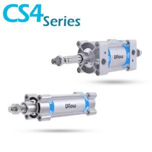
These are the numbers you'll get from catalogue tables for series like the CS4/CN4 Series or the larger-bore CS7/PS7 Series — but they're theoretical maximums at full line pressure, not what you should design a machine around. More on that below.
Why Retract Force Is Always Lower Than Extend Force
On the extend stroke, full pressure acts across the entire piston face. On the retract stroke, air enters the rod-side chamber, where the piston rod itself occupies part of the cross-section — so the effective area, and therefore the force, is smaller. Retract force = Pressure × (Piston Area − Rod Area).
The effect is largest, proportionally, on small-bore cylinders, because the rod takes up a bigger share of a small piston face. Using standard ISO rod-to-bore pairings at 6 Bar:
32mm bore / 12mm rod — retract force ≈ 415 N, about 14% less than extend
63mm bore / 20mm rod — retract force ≈ 1,682 N, about 10% less than extend
100mm bore / 25mm rod — retract force ≈ 4,418 N, about 6% less than extend
If your application needs equal or near-equal force in both directions — a clamping or press-fit operation that must release with authority — size the bore on the retract figure, not the extend figure, so both strokes clear the load with margin.
Build In A Safety Margin — Don't Size To The Redline
The catalogue force number assumes clean, fully-regulated line pressure, a new seal set, and zero friction losses — none of which hold up over years of duty cycles. Compressor pressure sags under peak plant demand, FRL regulators drift, and seal friction increases as cylinders wear. A cylinder sized to run at 100% of its theoretical force has no room to absorb any of that.
As a working rule, design your load so it never exceeds 70-80% of the cylinder's theoretical force at your minimum expected supply pressure — not the compressor's rated maximum. That margin absorbs pressure drop, friction, and the load variation that real installations always have, without forcing you to jump to an oversized, more expensive bore "just in case."
Stroke Length, Bore, and Column Buckling
Force capacity isn't the only thing that scales with bore — so does the rod's resistance to buckling under compressive load. On short strokes this rarely matters, but as stroke length grows, the extended rod behaves like a slender column, and a rod that's perfectly adequate in force terms can bow or buckle well before it reaches its rated load.
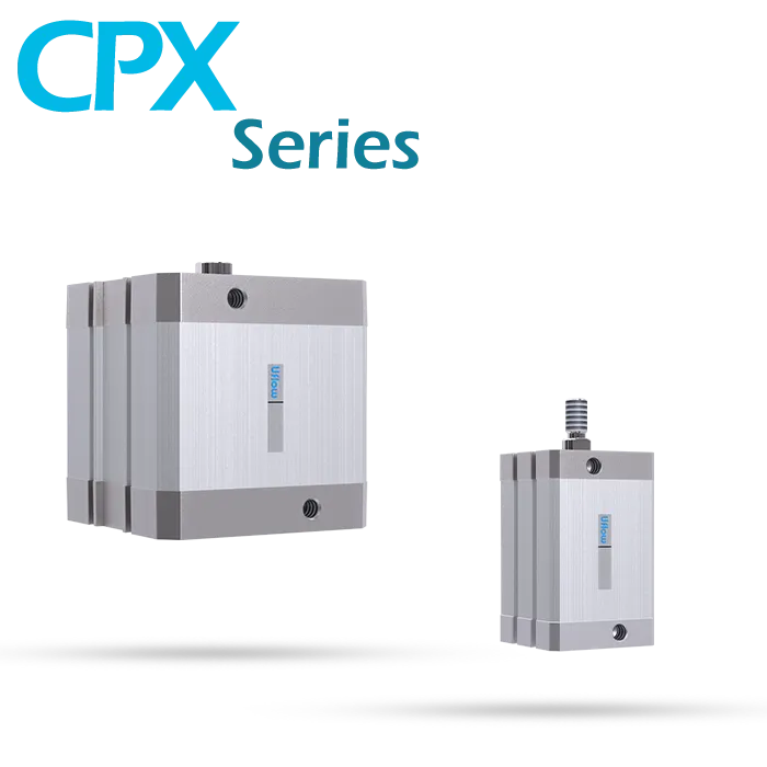
Two practical guidelines follow from this. First, on strokes beyond roughly 300-400mm carrying compressive load, check the rod manufacturer's column-strength (Euler buckling) rating for that stroke length, not just the force rating — many series publish a maximum stroke-vs-load curve per rod diameter for exactly this reason. Second, if a design calls for a long stroke and a heavy compressive load together, moving to a larger bore with a heavier rod — or specifying a stop-tube to limit unsupported rod extension — is usually more reliable than pushing a slim rod to its limit. The CPX/CPG/RXC Series covers long-stroke, heavy-duty applications where column strength is a real design constraint; for shorter, space-constrained strokes the CP/MXC compact cylinders are usually the better fit.
Cushioning: Taming End-Of-Stroke Shock
A piston travelling at speed and slamming into its own end cap generates a shock load many times the cylinder's rated working force — impact energy scales with the square of velocity, so even a moderate speed increase multiplies the stress on the end caps, mounting hardware, and the machine frame around it. Left unchecked, this shortens seal life, loosens mounting bolts over time, and eventually cracks end caps.
Adjustable pneumatic cushioning — a tapered cushion spear that restricts exhaust flow in the last few millimetres of travel — decelerates the piston before metal contact, and is worth specifying on any cylinder that cycles faster than roughly 0.3 seconds per stroke, or carries meaningful mass at speed. Both the CS4/CN4 Series and PS4/PN4 Series offer adjustable cushioning as a standard option — cheap insurance against a failure mode that otherwise shows up as intermittent, hard-to-diagnose wear.
Choosing a Mounting Style For The Load Path
Bore and stroke get most of the attention, but mounting style determines how the force you've just calculated is actually transmitted into the machine — and a mismatch here causes premature rod seal wear and bent rods even when the sizing math is correct.
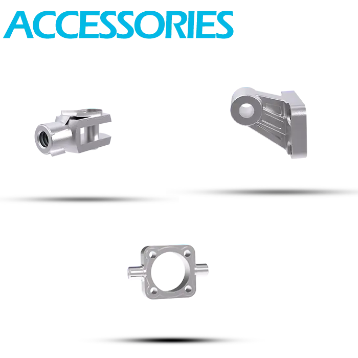
Foot mounting is the default for cylinders that push or pull in a straight line with the load fully supported and aligned — simple, rigid, and the lowest-cost option, but intolerant of any side load or misalignment. Flange mounting (rear or front) puts the mounting face in line with the thrust axis, making it the strongest option for high in-line push/pull force. Clevis mounting pivots at both ends and is self-aligning, which makes it the right choice whenever the load itself swings or the cylinder can't be perfectly aligned to a straight-line path. Trunnion mounting, with pivot points on the cylinder body rather than the base, is used when the cylinder itself needs to swing through an arc as the load moves — common on tipping, dumping, and clamping mechanisms. Standard brackets for all four styles are available through Cylinder Accessories, which also covers rod-eye and clevis pin hardware sized to match each series.
F = P × ADesign At 70-80% LoadMatch Rod To StrokeCushion High-Speed Strokes